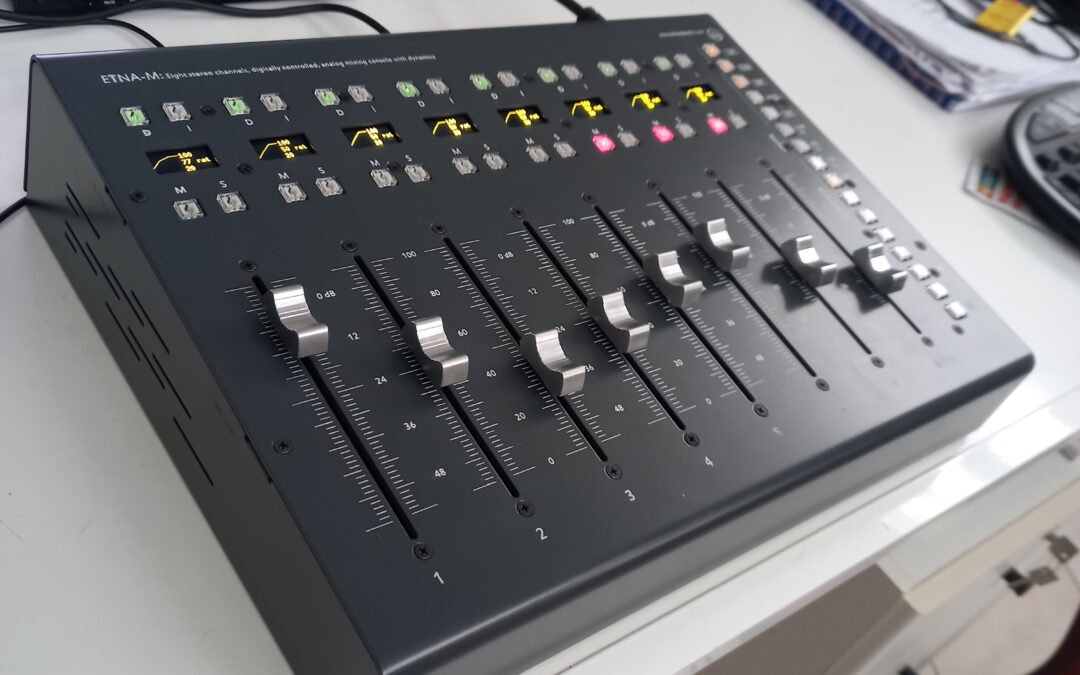
These are simple instructions for using your new Etna-M console.
Everything can be managed from the hardware interface.
Quick start:
- Connect two “D-sub (Tascam audio standard) to your-standard” cables from your digital_to_analog converters to Etna-M’s inputs. Two cables are needed to use all the eight stereo channels. Channels are distributed as follows: L1-R1-L2-R2-L3-R3-L4-R4 and L5-R5-L6-R6-L7-R7-L8-R8 (left and right stereo pairs, 1-4 through first connector, 5-8 through second connector).
- Connect two “TRS-to-your standard” cables from the outputs on Etna-M to a pair of analog-to-digital converters.
- Switch all the mute, solo, dynamics and insert buttons (top rows, above and under the screens) off.
- Mix by the faders.
- Calibration: reference points are set so to refer to “0 dBfs” if your A/D D/A converters are set to work with a +4dBu level reference. In this case, 0 dBfs on your DAW’s mixer are 0 dBfs on console’s metering.
The surface is ideally subdivided into three areas:
- Faders. They control every parameter for every channel (including the master bus, see below).
- Channel screens and enables (top row). The screens switch their function depending on current operation, channel buttons give direct access to: channel mute, channel solo, channel dynamics engage, channel insert engage.
- Control and parameter select buttons (right column). They are ideally subdivided into three groups (top to bottom): first five buttons are global enable controls (limiting, compression, expansion, inserts, ducking); last button at the bottom activates alternate functions, all the other (10) ones are for selecting the active parameter.
Every time one parameter is selected, the faders move to relevant position to show current values and give direct access.
When a parameter button is on, switching it off enables the normal mixing function for the faders.
IMPORTANT: the overall concept evolved even more while manufacturing the units, so we stuffed even more parameters behind the switches. Please add these to the list:
Alt – Compressor_threshold: Compressor model.
Alt – Compressor_makeup: Dry signal mix (on the editor a left to right shade on the dynamics display). NOTE: mix goes from 100% wet, 0% dry to 0% wet, 100% dry (actually a balance more than a “mix”).
Alt – Compressor_Release: Expander ratio (from <1 to >1, from gate to upward compressor).
To disable compression on master bus: double tap on fader 8 to toggle it to master channel; select Alt – Compressor_makeup (to control dry mix on the master bus); set the fader to max (dry only).
The faders are touch-sensitive. You can touch one to see current parameter’s value on the screen.
The eighth fader has a double function: channel eight and master bus. It is normally available to set channel eight’s parameters and volume (like channels 1 to 7). When the ALT button is engaged, the eight fader gives access to the master bus. Functions and parameters for the master bus are identical to those for channels 1 – 8.
Metering.
Etna-M has two sets of meters:
- Hardware, on the surface.
- Software, in the realtime editor.
The hardware meters, active while a fader isn’t touched, are subdivided into two parts: input level and dynamic gain bars on the left, output level needle on the right.
The input level bar shows input level in dBs referred to an ideal, abstract full-scale reference, on an 80 dB wide range. The absolute value of the levels depend on your setting for the digital-to-analog and analog-to-digital converters. You can set your own reference point once your system is set.
Left to right, following bars show: limiter’s gain reduction (top to bottom), compressor’s gain reduction (top to bottom), expander’s gain (top to bottom or vice versa, depending on how it is set).
The needle meter shows output level for the channel, with a tick step of 10 dB (see above for absolute reference levels).
The same metering is available, with higher resolution and frame-rate, on the software editor.
Software realtime editor.
The editor runs as a web page inside any modern web browser (NO internet connection needed). It requires the provided micro-USB cable to be connected from the unit to your workstation.
To access the editor, just type or copy-paste this address in the address-bar in your browser: http://192.168.7.2/gui/#Console (on Windows) or http://192.168.7.2/gui/#Console (on Mac). You can save the address as an icon on your desktop for further quick access.
The controls on the editor follow the hardware controls and vice-versa.
Total recall.
Once connected by the provided micro-USB cable, the unit should be visible inside your DAW (Digital Audio Workstation) as a MIDI input and a MIDI output device (with a name similar to “MIDI System”). Once you activate these modules, MIDI is transmitted/received between the unit and the DAW.
A complete dump of the state of the unit is sent periodically through MIDI on channel 16. To save current state, just create a MIDI track, arm it for recording from MIDI channel 16 from unit’s module and record a few seconds. You don’t need to hit the start of the dump, just ensure you keep recording for at least five seconds. Once saved with the project, this track sets the stored state of the unit when playing back (ensure you mute this track once the initial restore is done when reopening the project, otherwise all your further parameter changes will be overwritten and reverted to the saved state value).
Parameters and control changes.
Every single parameter change is sent as a MIDI control-change message.
Parameters for channels 1 to 8 are transmitted respectìvely on MIDI channels 1 to 8. Parameters for the master bus are transmitted on MIDI channel 9. The only parameter that is not transmitted as a control change is the fader position (for mix level), where pitch-bend messages are used.
Every parameter can be automated by keeping a MIDI track engaged for recording.
THe parameters will be controlled through MIDI once the track plays back.
Mixing, working levels and automation.
For the best resolution in a mixed-system setup like DAW+Analog-mixer, the digital-to-analog converters should be working close to full scale and the whole mix should happen in the console.
Etna-M includes two sets of volume faders: the first one (referred to as “Volume” in the parameters) if for the static mix and should be used to set the base, static levels for the raw mix; the second one (referred to as “Fader” in the parameters) follows previous one and should be used for mixing automation. “Fader” parameter is the one controlling the faders when all the parameter buttons (column on the right) are off.
So, to build a dynamic mix: set a base mix by the “Volume” parameter; perform dynamic mixing by “Fader” parameter.
Engaging the dynamics.
Etna-M features a full dynamic-control setup. The combined action of a compressor, a limiter and an expander (upward compressor or gate) gives an incredibly versatile control on the sound. Each section can be engaged separately, of course. Also, the limiter can work in compressor-mode in an optical-VCA combination of the compressor and limiter sections. Each section is multi-mode, giving access to a complete palette of dynamic behaviours from history of dynamic controllers. The dynamic section can be disabled at any time by a button tfor quick and effective checks on the results of the processing.
To engage the dynamics on a channel:
- Switch one or more of the global dynamics buttons (top-right).
- Switch the “D” (Dynamics) button for the channel (close to its screen) on.
Select the threshold parameter for the compressor (parameter select button on the right), set a low threshold to ensure you can hear blatant action of the compressor. Starting from here, set the parameters using the parameter buttons and the faders. To bypass the dynamics, switch channel’s “D” button off. To bypass a section (e.g. just the compressor) use relevant global switch (top-right).
Note: there are three available thresholds for the dynamic processing of a track (and for the master bus): Limiter, Compressor, Expander. Compressor’s threshold is absolute while Limiter’s threshold is expressed as dBs above Compressor’s threshold, Expander’s threshold is expressed as dBs below Compressor’s threshold. Even when the Compressor section is not used, its threshold shall be set as a reference for Limiter and Expander.
There is another complete set of dynamic effects on the master bus, for total control on the mix.
Ducking busses.
Etna-M includes a unique feature: full interconnection of channels’ side-chains through a set of four ducking busses.
The level envelope of one or more channels can affect the level of one or more channels, for a deep (e.g. bass-drum to bass) or subtle (e.g. drums and guitars) interaction among tracks or sets of them.
Each channel has a set of ten parameters for this feature:
- Send volume (called “Put” on the interface) from the track to bus 1-4 (four parameters).
- Receive sensitivity (called “Get” on the interface) from the ducking busses to the track (four parameters).
- Attack and release speed of reaction for the track to incoming ducking signal (two parameters).
To use the ducking feature:
- Switch the global Ducking button on (top-right).
- Set some Put value for a track to the first ducking bus.
- Set some Get value for another track from the same ducking bus.
- Compare the output with and without the ducking action by toggling the global Ducking button (top-right).
Note that a track can Put to and Get from the same bus, so obtaining a further dynamic control stage.