Vastaso Mark II is built on top of the first version, adding multiple channels, remote control, total recall, internal side-chaining and more.
QUICK START
- Connect inputs to channel one to a couple of outputs from your D/A converters, by means of two TRS-to-yourstandard cables.
- Connect outputs from channel one to a couple of inputs to your A/D converters, by means of two TRS-to-yourstandard cables.
- Switch both back-panel (light on) and front-panel (move to the right) power switches on. You can check the unit is powered because the needle of the big meter moves away from full CCW position. Wait a few seconds until the unit self-calibrates and the needle starts reacting to the Gain knob (even with no audio passing through).
- Starting point: Compression knob to 100%, Volume knob to 0%, Drive knob to 50%, Attack knob to position A, Release knob to position C, filter knobs to position F. Slowly increase output Volume, increase input gain while compensating by Volume knob until the needle moves with the peaks.
FULL SETUP
- First stereo channel is connected through TRS (balanced) jack receptacles. You can use channel one through four TRS cables (if your AD/DA converters have TRS receptacles) or TRS to X cables (where “X” is the connections your converters make available, e.g. DB25).
- External side-chain input, engaged through front panel switch, is connected through a TRS receptacle.
- Further two to four stereo channels are connected through DB25 female ports (Tascam audio standard). To access channels two to four you need DB25 to X cables. Simplest option is when your converters have DB25 connectors for ins and outs: a couple of DB25 cables is enough.
- Channel one is connected through the DB connectors, too. IMPORTANT: if you decide to access channel one through DB25, insert four raw (no cable needed) TRS jacks in channel one TRS ins/outs.
- Insert a raw (no cable needed) TRS jack in the external side-chain input when you want to use channel two (through DB25).
- Power input is universal (frequency and voltage).
- There is a double power switch: on the back panel (close to the power cable and the fuse) and on the front panel. Both need to be closed to power the unit (the front panel switch is redundant, for a simpler management when the unit is in a rack space and the back is not accessible).
- The unit is stand-alone. If you want to access its editor, connect the provided USB cable between the micro-USB port on the back panel and an USB port on your workstation. To access the editor, open your favourite internet browser (NO internet connection required) and type this address: http://192.168.6.2/gui/#Console__Vastaso (on Windows) or http://192.168.7.2/gui/#Console__Vastaso (on Mac). You can create a shortcut on your workstation’s desktop, pointing to this address, for future, easier access.
- The front panel controls most of the parameters of channel one. The parameters that can’t be accessed are: stereo link (that wasn’t available in the first version) and ducking busses (also, a new feature related to the channels being multiple).
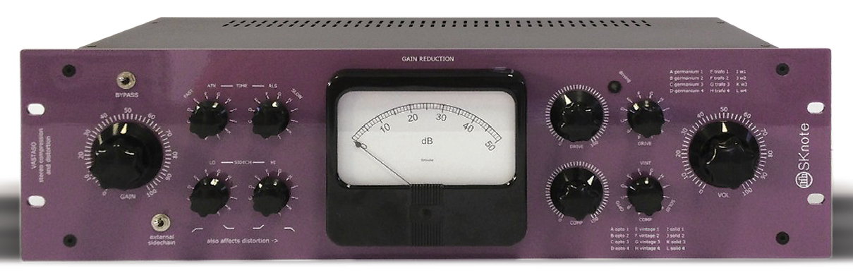
- IMPORTANT: The analog, needle meter on the front panel shows the control voltage of the Gain Reduction VCA. It includes an offset related to input gain and saturation gain (drive control) and dynamically moves of the Gain Reduction amount. This is useful to monitor the absolute working position of the VCA. The neutral position is referred to as 0dB. To monitor the amount of Gain Reduction, stop the incoming sound and check the static starting point. When setting the compressor, try to have the working position (no sound) quite close to 0dB on the needle meter. This ensures the best performance of the VCA. For detailed, multiple metering you can simply open the editor.
- The unit is fully hard-bypassed, so you can insert it in your chain and keep it there. It will hard-bypass (by means of relais, so: clean contacts) all the channels when switched off.
STEREO CHANNELS TWO TO FOUR
These channels are absolutely identical to channel one. The only difference is that they are controlled through the editor. Use them exactly like channel one. There is no relationship among the channels (until you start using the ducking busses, see below).
SAVING AND RESTORING THE SETTINGS
Vastaso Mark II sends and receives all its parameters through USB-MIDI, using the same single connection used for the editor (micro-USB).
To see it in your DAW, check the list of available (input and output) MIDI devices. Enable the ones (one for input, one for output) with a name similar to “MIDI system”. This enables the communication via USB-MIDI between the unit and the DAW.
Vastaso Mark II receives Control Change (CC) messages (all parameters, starting from CCN #1) on any MIDI channel and transmits on channel one. The whole list is sent periodically. To save the whole status of the unit, engage a MIDI track in your DAW and record a few seconds. The whole list of parameters gets recorded, available to be saved with the project. To recall the status when re-opening the project, just temporarily engage the MIDI track and play it while the unit is connected.
DUCKING BUSSES
Each channel is connected to four, common ducking busses, through its own send controls (labelled as “Put” 1 to 4). It can receive level control signals from the same busses, with individual return controls (labelled as “Get” 1 to 4). To control, for example, channel two from channel one’s envelope, set channel one’s Put1 to 50% and channel 2’s Get1 to 30%: the envelope of channel one will affect the level of channel two by some amount. The reason for separate Put and Get controls (instead of simpler direct sends) is that it is more versatile for more detailed combinations (e.g. multiple channels’ interactions). Notice that a channel can affect itself (by “Putting” to and “Getting” from the same ducking bus): this can be useful, for example, to use it as a limiter after the compressor. The ducking interaction happens AFTER the compression. Each channel has its own time constants for its overall “Get”. Note that the whole ducking system can be controlled only through the editor.
SATURATION NETWORKS
Vastaso MarkII include the same exact saturation networks from the original model. Now, they can be selected from remote and are multiplied by four (eight sets for four stereo channels). These are actual networks (not models), that include silicon and germanium components, FETs, transformers, LEDs in complex configurations to offer a wide palette of saturation curves and stereo reaction (some networks have a wider effect on the stereo image, due to a wider variation in components’ response between left and right channel). Ther saturation networks are preceded and followed by complimentary gain stages (pre and post, with opposite gain), controlled through the Drive controls.
COMPRESSION MODES
Parameters for the twelve compression modes (again, completely independent pre-channel) have been expanded, including a left-right link parameter (continuous, in the style of API 2500 (registered trademarks), multiple release time constants. The other main variables are: topology (feed-back or feed-forward), detection (RMS, peak or peak/RMS differential), compression curve (or “knee”), frequency response of the side-chain, time-variance of the frequency response of the side-chain and more. The best way to deal with this is to get used to some modes and acquire some experience with each one, for quick selection depending on the target.
SIDECHAIN FILTERS
The side-chain filters affect the response of the compression to the frequency content of audio. A boost in a frequency region causes a stronger response to that range, a cut causes a weaker response. There are two filters: low frequencies and high frequencies. Their frequency range is affected by the settings, together with their gain (roughly: lows control the bass guitar and bass drum region, the highs control the snare drum region). Note how the two controls are arranged on the front panel: the low filter decreases CCW (counter-clockwise) and increases CW (clockwise), the high filter increases CCW and decreases CW. Just imagine holding the extremes of the frequency spectrum with your hands and bending it. “F” is neutral position. Note how the sliders in the editor follow the same convention: lower value corresponds to CCW, higher value to CW.